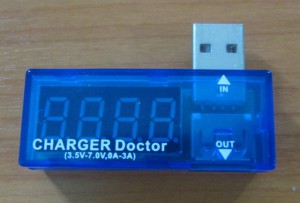
During use of the new power box, I found that it wasn’t charging some phones properly. In many cases when it was charging, if you attempted to use the phone it would slowly discharge. I put this down to the micro USB cables being inadequate or damaged, but recently I got a device which proved otherwise.

The USB charger doctor is a small device that sits between a USB socket and your cable. It shows you the voltage of the USB port and the current your device is drawing. This is useful in many respects from checking the voltage is in spec to seeing how much current your device draws under different conditions.
During my testing I found that my phone would only charge at around 0.48A and the voltage would dip to 4.5v. This voltage drop should never happen unless the regulator was being overloaded, which given it is capable of 3.0A I knew it wasn’t. The same happened for all 6 USB sockets on the power box. I also tested it on my PC and on the regular phone charger. The PC gave 0.5A (expected) and the phone charger gave 1.25A, it’s normal output current. But for the PC and phone charger, the voltage did not drop to 4.5v, it stayed around 4.9-5.0v.
This got me thinking about the current rating of the USB sockets I had used. The cables on the moulded sockets are fairly thin but should still be capable of 1.0A surely? My testing showed not. Under load, the regulator showed 5.0v but the charger doctor showed 4.5v at the socket, so the voltage is definitely dropping over the short length of cable from the regulator to the USB sockets.
I have no idea how to remedy this other than to use PCB mount sockets and run my own custom cables which I know will cope with the current I need. I tested a PCB socket and it managed 0.8A at the time of testing and with no voltage drop, so presumably that’s all the current the phone wanted at the time. This is still better than the existing sockets.
My biggest issue now is integrating the new sockets. I have decided to use dual USB sockets rather than singles but this shouldn’t matter massively. The ones I have ordered are not right-angled sockets but rather they stick straight up on the PCB. That will allow me to fabricate some form of mount for the front panel and hopefully make it easy to do with m3 screws.
In the mean time, I will probably just make up a temporary charging board and use the old 1A regulators from the first power box so we have some higher power sockets when needed.
I’m disappointed that I didn’t catch this earlier but that’s what prototyping and having this as a hobby is all about!


