Joule Thief Circuit – Power a white/blue LED from a 1.5v battery

Posted by under Electronics, on 6 June 2012 @ 10:32pm.

I’ve seen this circuit around before, but it kept cropping up while looking at other electronics videos on YouTube. It’s called a Joule Thief, and it was designed as a simple solution to boost voltages from lower sources higher at the expense of more current draw.

This circuit is basically a DC to DC boost converter that uses a ferrite toroid coil and a transistor to oscillate. I’m not 100% sure on how it works yet (even though I built one but anyone can do that!) but there are two coils on the ferrite toroid which are connected in parallel. When oscillated they produce more voltage than went in as mentioned above at the expense of more current being required (remember the equation, power = volts * current (P = V * I). More double the current and half the volts is the same overall power). The transistor is what causes the oscillation by switching very quickly.

Here is a basic diagram I found on evilmadscientist.com.

Joule Thief Circuit Diagram

You should be able to follow that quite easily. I would put a diagram on of the layout I used but I don’t have that picture to hand. Perhaps on my next blog on this I will put that on but a quick search should find you suitable images to work from.

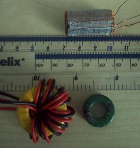
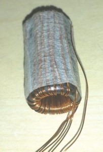
Here’s the ferrite toroid I used (and a bunch of others next to a ruler for size comparison). I wound it myself using ~0.25mm magnet wire and held it in place with sticky tape. The diagram I found used 20 turns but I ended up with 26. It still works pretty well. In fact I would have preferred more turns as when the voltage got too low on the input the output also dropped, thus the LED light output dropped drastically.

Ferrite Toroid CoilFerrite Toroids


When the coil is wound you need two strands, so one long length folded in half. When winding, leave a few inches at the joined end and wind the rest both strands at the same time side by side (as you can see above). The end that is joined to both strands will become your positive input for both coils. The others are then connected to the base (through a 1k resistor) and the collector of a general purpose NPN transistor. The emitter is where your higher output will be.

There is likely some math behind the number of turns the coil needs given your input to get the required output. I haven’t discovered or looked this up yet. If you just want to power a white LED from a 1.5v battery, then 20-30 turns will suffice. I worked it out as 0.1v per turn but this might be different between ferrite toroids.

The beauty of this circuit is that it will work at very low voltages and will extract all of the power from your battery until it’s completely dead, not like most applications which will drop off at around 1.0-1.3v. This still leaves a lot of power left in the battery (up to 40% depending on brand!).

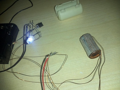
Here is my setup, as messy as it looks. This was my first test and I will be building more in the future which will be on a circuit board (actually it will be on veroboard (stripboard)).

My Joule Thief Circuit


Arduino – A step up from Picaxe?

Posted by under Electronics, on 19 December 2011 @ 8:37pm.

A friend of mine recently bought an Arduino Uno after I mentioned it in a conversation. It’s much the same as a PICAXE but it is designed to be much easier to program (even though the PIXAXE was programmed in BASIC which wasn’t really so basic). I decided it would be fun to try it as well because it has something called an Ethernet Shield (a shield is just an expansion or add-on board).

The Ethernet Shield allows you to connect it to the Internet. This allows you to do so much more with it, and that’s where I got the idea for basic home automation. My first idea was to control a light to begin with and work my way up from there. I’d like to make a remote reset system for my home server set up. I’d like to make it so I can reset the server remotely should it be required.

This got me thinking of other ideas as well such as a weather display (I’ve seen a few of these around) or a server monitor for my server in France and at home. I’ll probably think of even more ideas along the way as well as there are so many “shields” you can get for the Arduino, including GPS, GSM (mobile phone), LCD screens and more.

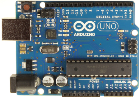
ArduinoUno
Source: Arduino.cc

I’ll be updating the blog with my progress once I receive my Arduino and Ethernet Shield, and I will probably post code that I use as well. Hopefully it won’t take too long to get used to as it looks much like PHP code that I’m familiar with.


5v regulator based on LM2575

Posted by under Electronics, on 5 December 2011 @ 10:37pm.

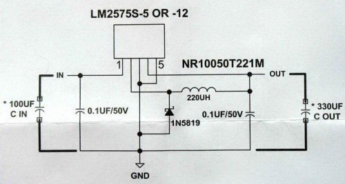
Here is the final circuit I used as a basis. Some of the components have been subsituted:-
– 220uH substiuted for 200uH (best I could find for 1A output)
– 100uF substiuted for 330uH (what I had to hand)
– 0.1uF left out

LM2575

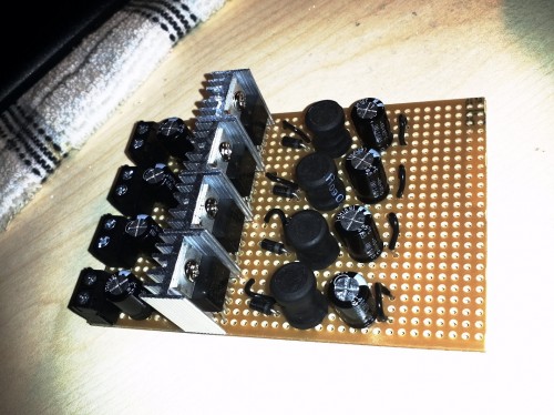
Here are the 4 separated circuits on a single board:
4x LM2575 - Final design

The heatsink at 85% load (850mA) gets hot but not hot enough to burn you when you touch it. This is much more efficient than the LM7805 which got too hot to touch (it actually melted my breadboard).

All that remains is to add some output connector blocks and the board is complete. I can then move onto the smaller board which will house the voltage divider. This will be mounded behind the switch for each of the USB ports.

More to come.


LM7805 5v Regulator For USB Phone Charging – Prototype 1

Posted by under Electronics, on 10 November 2011 @ 10:20pm.

Right! Now that I have finally solved the issue on the charging here is prototype 1 of the circuit.

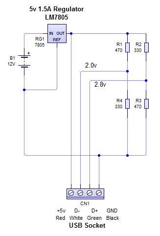
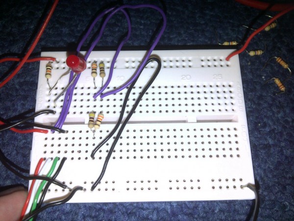
It uses 2 voltage dividers to give 2.0v to D- and 2.8v to D+, which allows smart(er) phones to take a high current. 1A should be allowed with this setup. If you want 500mA maximum, set D+ to 2.0v just as D- is.

Note: The smoothing capacitors have been excluded from this circuit but will be included in the final design. 470uF on the regulator input, 330uF and 100nF on the output of the regulator.

Working Prototype 1 circuit diagram

Working Prototype 1

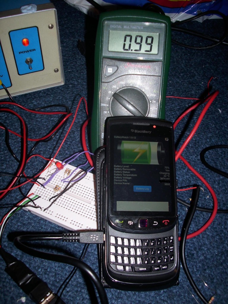
The meter is connected to the output of the regulator so it shows the current flowing to the phone.
Charging proof


A Case Of Fault Finding

Posted by under Electronics, on 9 November 2011 @ 11:52pm.
usb-logo

One of my current projects is building a 5v USB regulator for charging mobile phones. I’ll be using this when away camping so myself and friends can charge their phones whenever they like at full speed. My previous solution was a cheap cigarette socket version which only supplied 1A between two sockets. This custom version will provide 1A to each socket, of which I’ll have a total of 4.

Now from the beginning I thought “this is going to be easy!”. After all it’s just a regulator, some capacitors and some resistors. I connected up a nice basic circuit with an LM7805 5v 1.5A regulator. It was solid as a rock on 5v and could easily supply 1A. 1A is more than enough to charge most phones, and my mains charger only outputs 0.7A. However, try as I might, I could not get the phone to accept a decent charge.

It would start off at 0.5A, then fall to 0.1A and often drop off completely. I was getting really frustrated. I’d tried dozens of techniques I’d found on the web for connecting the data pins with different value resistors etc. None of them worked! I even tried another phone to no avail. I thought my circuit was to blame and I wanted to know what I was doing wrong. Subsequently I hacked open my genuine blackberry charger to see what on earth was going on inside. It turns out nothing special was going on inside.

So I wasted a perfectly good blackberry charger for nothing (not that I ever used it but that’s not the point). By this point I’d spent over 8 hours trying to get this working and I even went to the trouble of posting on a forum and e-mailing a guy on youtube who I though may have the answer. He turned around and said he doesn’t answer personal project questions like that – fair comment. Being a knowledgeable guy he probably gets too many of them anyway. He told me to post on his forum so I did. It was at that point a friend of mine suggested something…

It’s the most stupid thing ever, but he suggested trying another USB cable. So I did…

Straight away I was getting 1.07A charge rate into the phone, rock solid. In 1 hour it was fully charged and didn’t flicker or fault once the whole time. I cursed like I have never cursed before because it was such a stupid thing not to check for in the first place.

I haven’t looked into why the cable I was using wasn’t working properly but it would explain why I had so many issues using it to sync to the PC. I always thought it was the phones fault but it has to have been the cable. It all makes sense now.

So what’s the moral of the story? Always check everything, even the stupid things like USB cables. You can’t easily diagnose a cable so just swap it out and rule it out as a possible cause. My guess is there is a small break in the cable causing intermittent problems, or there is a bad connection on one or more contacts. Without testing it I can’t be sure but suffice to say the cable is now deemed out of action.


5v L7805 Regulator Heatsink

Posted by under Electronics, on 21 October 2011 @ 5:34pm.

A recent project of mine is creating my own 5v regulators for charging mobile phones, etc. This will be incorporated into a battery box which I and my friends use when camping. However on this years trip we burnt out the 5v regulator we were using. For that reason I decided to make my own that would be more robust in comparison.

The biggest hurdle I’m hitting so far is dissipating enough heat away from the L7805 regulator (12v to 5v @ 1.5A). I am currently avoiding buying a “proper” heatsink for it as they cost in excess of £3 each. The regulator itself cost about 15p! It has been suggested by a friend that I use a “buck” style regulator instead which is significantly more efficient and does not require as much heat dissipation. This will likely be what I look at if I can’t find a suitably cheap solution to this issue. However as those themselves cost almost £3 each and require no heat sink in many cases it may be the better option.

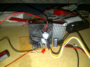
At the moment I have been using strips of aluminium attached to the 7805 regulator along with heat paste (the same kind used on computer CPU’s). It extracts the heat just fine but the aluminium on it’s own isn’t enough to keep the temperature low. The load I am using on the regulator is just a 25w peltier chip (it’s the device that keeps portable fridges cool). However as a friend pointed out it won’t be running at 25w because of the lower voltage.

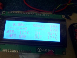
I have used 3 pieces of aluminium so far to extract the heat away and it seems to hold at a steady 90*c at 680mA, but as it’s not at full power, this is not going to be enough. I want to be able to extract at least 1A from it and still be below 90*c. A fan does aid this and keep it around 50*c but I’d prefer to omit the fan if possible.

5v regulator with home made heatsink
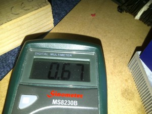
5v regulator current 5v regulator temperature (IN)

I’m considering ordering one of the buck regulators (LM2575 by the way) for testing. However everywhere charges a fair bit for postage so I’ll wait until I need other parts too.


« Newer Posts