5v regulator based on LM2575

Posted by under Electronics, on 5 December 2011 @ 10:37pm.

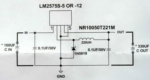
Here is the final circuit I used as a basis. Some of the components have been subsituted:-
– 220uH substiuted for 200uH (best I could find for 1A output)
– 100uF substiuted for 330uH (what I had to hand)
– 0.1uF left out

LM2575

Here are the 4 separated circuits on a single board:
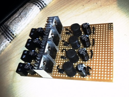
4x LM2575 - Final design

The heatsink at 85% load (850mA) gets hot but not hot enough to burn you when you touch it. This is much more efficient than the LM7805 which got too hot to touch (it actually melted my breadboard).

All that remains is to add some output connector blocks and the board is complete. I can then move onto the smaller board which will house the voltage divider. This will be mounded behind the switch for each of the USB ports.

More to come.


LM7805 5v Regulator For USB Phone Charging – Prototype 1

Posted by under Electronics, on 10 November 2011 @ 10:20pm.

Right! Now that I have finally solved the issue on the charging here is prototype 1 of the circuit.

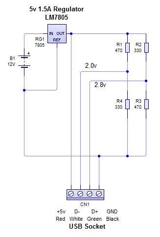
It uses 2 voltage dividers to give 2.0v to D- and 2.8v to D+, which allows smart(er) phones to take a high current. 1A should be allowed with this setup. If you want 500mA maximum, set D+ to 2.0v just as D- is.

Note: The smoothing capacitors have been excluded from this circuit but will be included in the final design. 470uF on the regulator input, 330uF and 100nF on the output of the regulator.

Working Prototype 1 circuit diagram

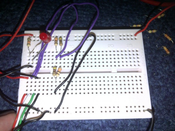
Working Prototype 1

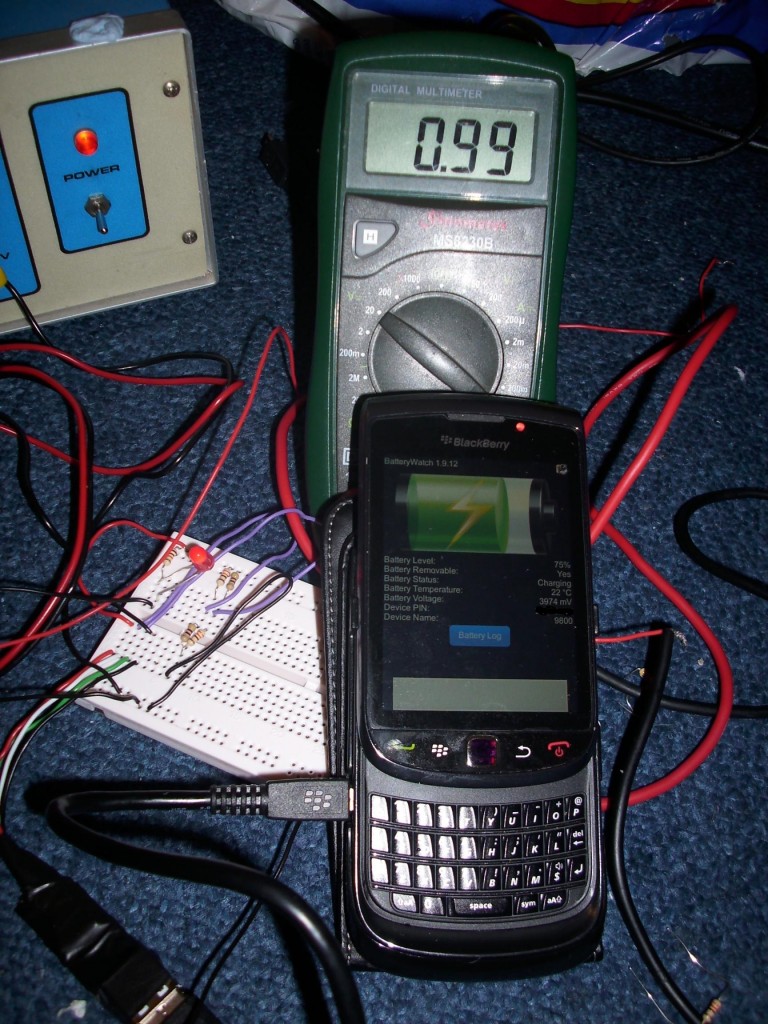
The meter is connected to the output of the regulator so it shows the current flowing to the phone.
Charging proof